
 What this is about
Design exercises cost you nothing and are good for thinking. This is just a design exercise. No real calculations have been done, no models have (yet) been built.
I've sailed Wharram catamarans a lot, and presently own one. They're very good boats for the waters I sail. But every owner of ervery boat can think of things they would change. This exercise is based on my views of whats good (and what's not so good) about my present boat for my waters (fast tides and shallow sandbanks).
I appreciate that I'm missing one of the great virtues of the Wharram boats, namely their simplicity and low-tech approach. I'm missing it because I personally don't value it. Equally I'm putting the flexibility that Wharram values so highly as a minus point. I personally just don't see it. The flexible boat suffers much more chafe and wear, cannot have a taut jib luff and consequently is compromised as a sailing boat.
In fact most of the faults I'm talking about are the faults of her virtues; the slab-sided appearance is a by-product of the very simple build, the poor resolution of stresses is a by product of the low-tech design. Nevertheless, when the boat hobbyhorses and repeatedly slams heavy loads into a bridle attached to the stemposts and a wooden block 'chainplate' attached to the outer gunwhale halfway between the beams, I wince.
Poor manouverability is at least partly a consequence of small rudders, and small rudders are more or less inevitable if you are going to be able to sail the boat in very shallow water, which I need to do.
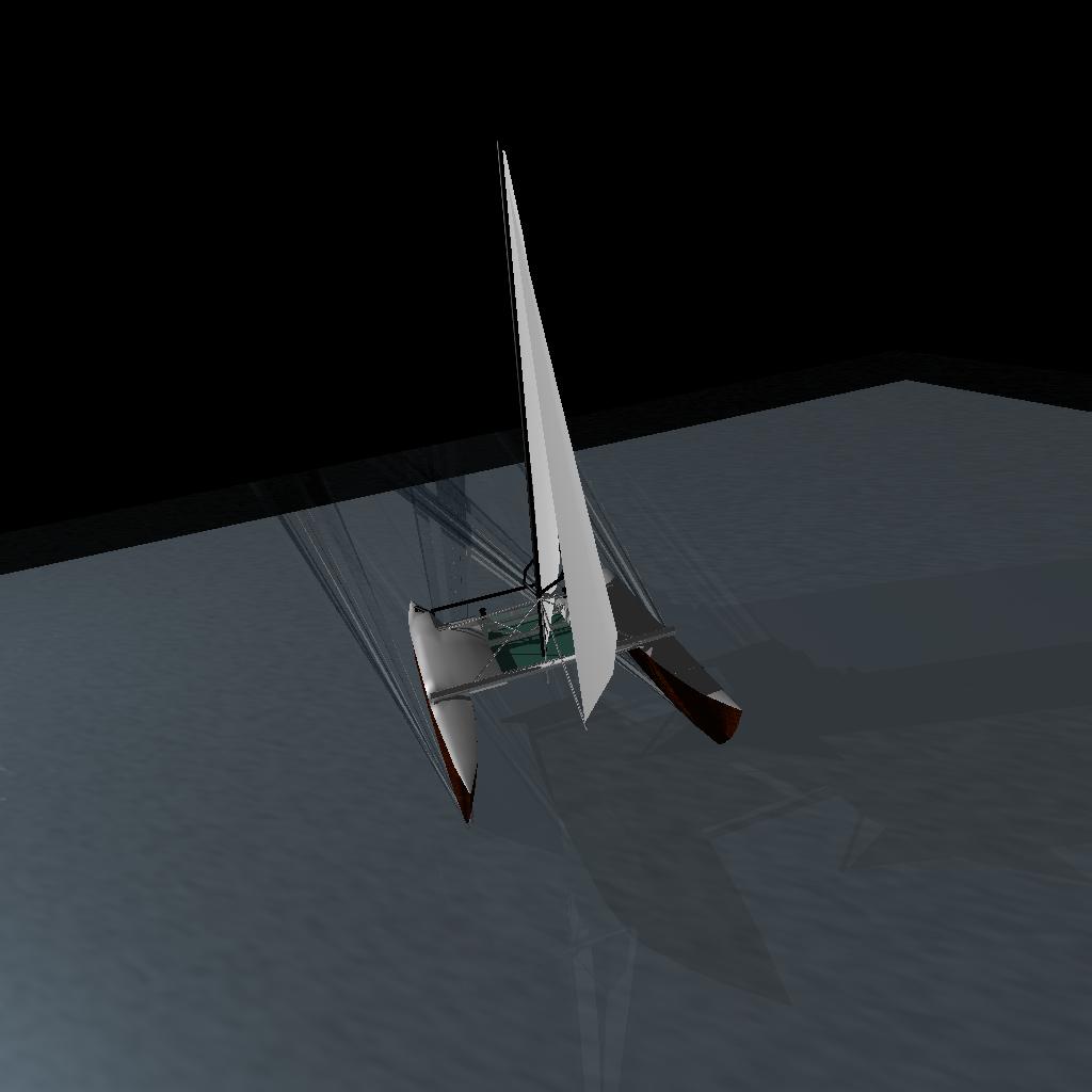
What I'm trying to achieve in this exercise is a fast, light cruising catamaran with better manouverability, better performance and (arguably) better looks, while retaining the shallow draft, accommodation and sea-kindliness of my present boat.
 The rig and the stress frame
The weak point of the modern catamaran, with the mast mounted on a beam between the two hulls, is the main beam. Any failure of the beam not only means the loss of the rig, it seriously compromises the structural integrity of the whole boat. The beam is horrendously stressed, and takes an enormous load at precisely the worst point. This cannot be a good thing, and one of the main things I would want to do in building my own catamaran would be to get rid of the mainbeam. Some thirty years ago I recall reading a proposal for a stress-frame catamaran rig in an AYRS journal. Since then I haven't either seen or heard of a boat rigged in such a way, which is surprising because the idea seems so sensible and so obvious.
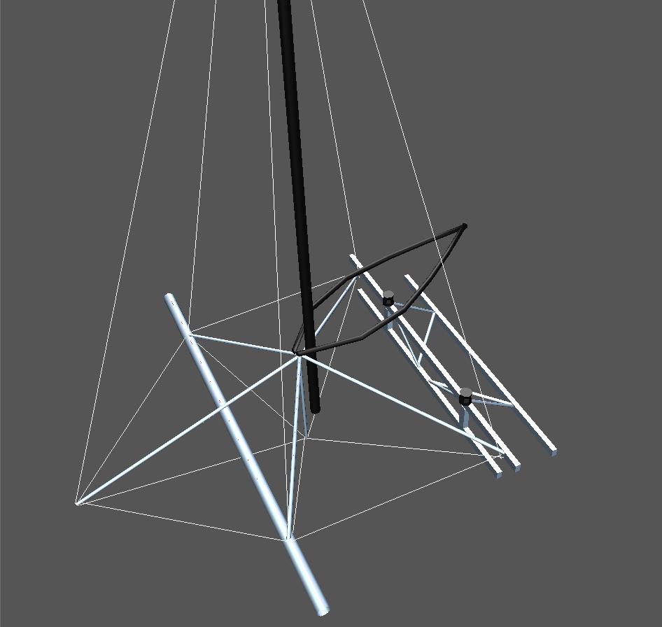
This design has a pentagram of five lateral struts and a dolphin striker supporting the mast step. Stays run from the masthead to the outer end of each lateral strut, from the outer end of each lateral strut to its adjacent strut on each side, and from the outer end of each lateral strut to the lower end of the dolphin striker. The after two lateral struts are attached to the torsion frame. The middle two struts rest on a forebeam, although I believe this is structually more or less redundent and a racing design might dispense with it.
The pentagram struts may be either aluminium or carbon fibre tube. They are in pure compression. Obviously special fittings will be required at the ends, and I haven't given a lot of thought to how they would be fabricated.
The pentagram resolves all the rig stresses, but it doesn't stop the hulls twisting with respect to one another. The second element of the stress frame is the torsion frame. The critical part of this is a vertically oriented web preventing the hulls from rotating about their fore and aft axis. The pentagram should effectively prevent rotations around the vertical and lateral axes, but because the cockpit area needs a solid floor ithere didn't seem to be much lost by providing an additional, horizontally oriented web. This also provides some structural integrity while rigging the pentagram or in the event of its failure.
I envisage the torsion frame as being a welded aluminium structure comprising three box section beams - upper, lower forward and lower aft - running across the boat, connected by box section members running perpendicular to them and smaller, circular section members providing diagonal bracing. The three primary beams are attached to strong bulkheads firmly bonded into the hull at each end. I envisage the torsion frame being about 600mm tall and about 1500mm fore and aft. Across the boat it fills the width between the hulls, which is between two and three metres.
 Sails and the stress frame
The stress frame isn't perfect. The mast cannot be completely in column with the dolphin striker, unless it is the same spar. It might be OK for it to be the same spar on a beach cat, but at the size I am working (about nine or ten metres) I just don't see how you could step it and rig it. Consequently I envisage a strong bracket attached to the forward side of the mast and resting on the top of the dolphin striker. The mast isn't completely in column, but as the loads imposed on it by the mainsail prevent it being a pure compression strut anyway I'm reasonably relaxed about this.This solution does not, however, provide room for the mast to rotate, unless the hub fitting of the pentagram is very wide which makes it much more complex to fabricate. I'm not too stressed about the mast not rotating, because I'm very much impressed with the sleeve luff sail on my Tiki, and think this is an excellent solution.
There is one complication, however: the position of the mast support bracket being considerably above the foot of the sail, there needs to be a cut out in the sleeve to accommodate the bracket. Furthermore, to allow for reefing, the cut out needs to be fairly long. I envisage the actual strain being taken on a series of straps and buckles (as, indeed, it is on the Tiki sleeve luff sails), with a flap per reef to cover the cutout which velcros on to provide clean airflow when not reefed.
If a wishbone boom - as shown on the concept drawings - is used, and the rig stresses are to be resolved to the stressframe (which after all is the point) then there need to be two mainsheets, one from each end of the top rail of the torsion frame to the wishbone leg on the same side. I like the idea of the wishbone because it controls twist without complexity, but a conventional boom sheeted down to a track on the top rail of the torsion frame would be simpler.
Another complication is bringing the run of the jibsheet down onto the stress frame. Ideally it should come to the top rail of the torsion frame, but this means that the clew must be cut higher than is currently fashionable (or else that you have very considerable overlap). This could be got around by positioning the jib sheet block on a span between the aft and middle legs of the pentagram, but I'm quite relaxed about a high cut clew. A compensating factor is that the tack can be taken considerably lower than is possible on conventional catamaran rigs.
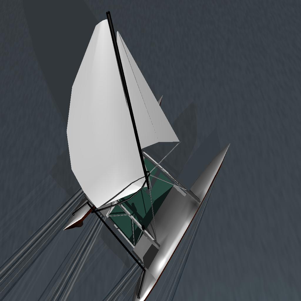
I've shown a battened windsurfer type sail on the concept drawings rather than the sleeve luff gaff on the Tikis. The sleeve luff gaff has a lot of benefits, but (in my opinion) needs battens to control the shape of the rear half of the sail anyway, and without a boom has a poor shape off the wind. Once you've added battens and a boom the sleeve luff gaff becomes more, not less complex than a sleeve luff bermudan.
My intention is to have a light, easily driven boat with a modest sailplan. She should (in my opinion) be able to carry full sail into force five without risk of capsize. Without having run the numbers my feeling is that at nine metres she would carry about 30 square metrres of sail, with another 30 square metres in an asymmetric spinnaker. The jib would be roller reefing and the main would have two slab reefs.
Obviously there's nothing to stop someone else using the same concepts to produce a much more adventurous rig, but that's not my objective.
 The hulls
To go to windward in very shallow water, without fear of damage on hitting mud at speed, imposes fairly sharp limitations on hull design. Daggerboards are something I want to avoid if possible - although all sorts of solutions have been tried, if a boat with daggerboards hits bottom at speed the leverage imposes stresses on the hull which will do damage unless very heavy reinforcement is used. Folding centreboards have two strikes gainst them - one, the long slot induces parasytic drag, and two, the case and associated mechanism takes up just too much space in the wrong place in a long narrow hull.
So the hulls have to resist leeway on their own, as a consequence of their own form.
Wharram's deep, narrow V hulls do do a very good job of resisting leeway, and my perceprion is that the leeway angle of my Wharram is quite small. But is it possible to do better?
Many traditional pacific proas and double canoes have hulls which are markedly assymetric in cross section. This makes some sense, since the lee hull of a catamaran is more depressed and has a better grip on the water, whereas the windward hulls is relatively lifted and has less grip. A hull with creater convexity on the inner side - as is traditional - would act as an extremely low aspect foil lifting to windward. Of course you'd normally expect such a low aspect foil to suffer so much from tip loss as to be fairly useless, but the surface piercing aspect may affect this. Certainly it would be surprising if so many traditional builders had adopted this feature if it had no merit.
Of course to effectively resist leeway without bords the asymmetric hull must also be deep and narrow, like a Wharram hull, and must in consequence have more skin drag than one with semi-circular underwater sections. This is not a recipe for building an all out racing boat, although obviously I want her to be fast.
It's worth noting in passing that any convexity of the sections below the waterline means that either the hull must be shallower (have less lateral plane) than the equivalent Wharram hull or must have heavier displacement than the equivalent Wharram hull. Wharram's designs are often seen as crude and primitive, but this is a mistake. Of course, building a hull with Wharram style simple curved panels below the waterline and complex curves above it seems perverse, but it may be the best way to get the combination of looks and shallow water performance I want!
Asymmetric hulls have been very rare in modern western catamarans. Some of the early CSK catamarans had this feature but I don't know of any others, and Rudy Choy's current boats don't have it.
So what's wrong with asymmetric hulls? Well, of course, they're going to be more difficult to build. I expect that, theoretically at least, you could torture ply into a nice asymmetric hull but you'd have to be very adventurous. Similarly it shouldn't be hard to build an assymetric hull using constant camber or cylinder mounding - except you'd have to have two different moulds fot the inner and outer hull sides respectively.
I had originally thought of having the hulls symmetrical fore and aft, so that both could be built on the same mould. However, some people have suggested that the reason Wharrams hobby horse so badly is that the bows and sterns have the same harmonic frequency, and the reason fine entry/broad stern cats don't hobby horse so much is that the ends have different harmonic frequencies and each damps out the other's pitch. I find this persuasive.
Furthermore, of course, if you watch an nine or ten metre Wharram sailing, the major movable weights - the motor and usually most of the crew - are aft of midships and the lack of additional bouyancy in the sterns leads to slightly stern-down trim.
So my revised ideas call for fuller stern sections. This means that either you need two completely separate moulds for the two hulls, or else after building the first hull you completely disassemble the mould and reassemble it the other way round. Either solution adds complexity to the building process.
Of course if you built with flat ply panels on a frame in Wharram fashion all this complexity is avoided, and indeed the assymetric hull should be no more complex to build than a symmetrical one, and the underwater body would quite closely approximate the lines I'm currently planning - but you'd end up with a very slab-sided looking boat and in an ideal (design exercise) world that's something I'm trying to avoid.
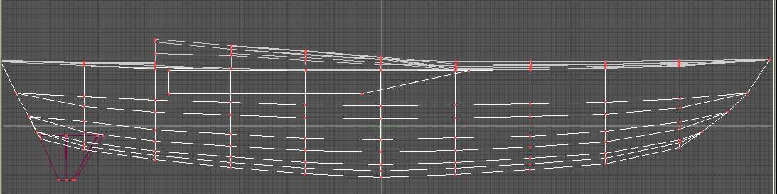
If I were building her now I would strip plank in a female mould. After the first hull was complete I'd disassemble the mould, reverse all the sections and reassemble it for the other hull.
 Rudders and Steering
My Wharram has a definite deficit in the steering department, especially at high speeds. Air sucks down the low pressure side of the rudder making sudden manouvres at high speed very uncertain, and generally the turning power of the rudders isn't good.
Kickup rudders with a higher aspect ratio would be a partial solution but would still suffer from air entrainment. A better solution, it seems to me, would be to move the rudders under the hulls where they should be relatively immune to entrainment. The question then arises whether the rudders and skegs should extend below the lowest point of the keel. On the visualisations they do very slightly. If they were to extend any further below the keel line I think that a kickup mechanism would be required, which for an under hull rudder would be very complex. Whether the rudder shown would have enough area to turn the boat I honestly don't know.
Obviously the rudder stresses are transmitted to the hulls. There's nothing I can really do about this; there's no obvious way of extending the stress fram sufficiently far aft to take the rudder loads. So the hulls are to some extent structural members rather than pure floats. That's inevitable. The hulls are also the leeway-resisting foils, and leeway resistance is precisely the force that the torsion frame exists to handle; the hulls have to be robust and rigid enough to transmit the leeway forces onto the stressframe. They also have to be robust enough to withstand the force of wave impacts and minor collisions, so handling rudder loads is not a major additional imposition.
 Living in a long lean hull
To be able to manage a boat in reasonable comfort you need
(Ideally you also need somewhere comfortable and sheltered, out of the weather, where the whole crew can relax and share a meal together, but I just don't see how you can achieve this on a nine or ten metre catamaran without hopelessly compromising her sailing ability).
All this is hard to manage in two Wharram hulls. On my 26, the galley has to be removed to access stores in the aft end of the port hull, and the navigation station has to be disassembled to access the berth in the starboard hull.
But, contrary to what other designers claim, for a given waterline beam a Wharram hull actually has the most internal volume of any modern catamaran design, and as we know waterline beam - fineness - is key to wavemaking and consequently to catamaran performance. A more graceful shape will have less, not more, internal volume. How do we achieve better accommodation in a narrower hull?
Malcolm Tennant's Tourissimo 9 (also concieved as a fast spartan cruiser) manages reasonably well, but at the expense of considerable height - he has standing headroom in the galley - and consequent windage. He also has his forward bulkhead quite far forward. I have to have a sturdy bulkhead under the middle pentagram leg and would like that bulkhead to be watertight, simply because in the event of a collision the unsupported forward end of the hull is vulnerable.
But among Tennant's design paramaters for Tourissimo is that she should be trailerable. I don't need that (frankly, if anyone wants to trailer-sail a twenty-eight footer they're welcome,. in my opinion - I shan't be trying it). Trailerability requires that the overall width of the disassembled boat be not more than about 2.75 metres depending on jurisdiction, and this means that the individual hulls must be less than half this. Of course, for fineness reasons the individual hulls will be less than this - in my case, about one metre each. But I can't pack the accommodation I need into two box which are about 5 metres by 1 metre by 1.5 metres high.
My solution to this is to put a blister on the inner side of each hull, with its underside level with the underside of the torsion frame - about 500mm above the load waterline. This will slam occasionally, of course, but you can't have everything. The blister I've shown on the concept drawings is pretty crude and punt shaped.
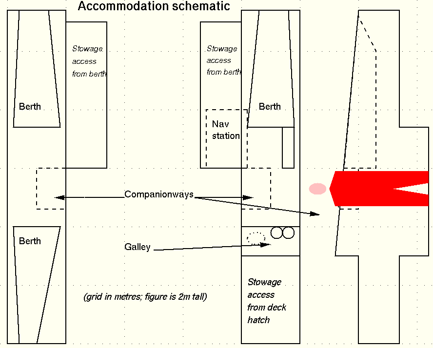
The accommodation design is based on the idea that when single handing you will live in the starboard hull. The galley is immediately abaft the companionway, so that you can cook standing up, or sitting on a folding seat. Food for immediate use would be stowed in a locker below the galley, with a flexible watertank under the floor. You can con the boat standing in the companionway. Because of the torsion frame the main bulkhead is immediately forward of the companionway, and the navigation table immediately forward of that in the punt. One can work either sitting on the head of the bunk or on another folding seat. The remainder of the punt provides stowage for dry clothing, books etc, accessible from the bunk.
There's no room or obvious place for a wet locker, but hooks to hang we oilies could be mounted on the outer side of the hull immediately aft of the main bulkhead, and draining into the bilge. This would keep wet clothes reasonably away from the berth.
A number of arrangements are possible in the port hull. One is to put a double bunk across extending into the punt to get width. The issue with this is that you would not have full sitting headroom in this bunk unless either the floor of the punt was undesirably low or the coachroof was undesirably high.
Another arrangement would be to replace the after berth shown on the schematic with a marine toilet immediately aft of the companionway. The after berth is a bit problematic anyway both because it has to pass through the after structural bulkhead and because it will be pretty narrow at the foot end.
The accomodation occupies 4.6 metres of the nine or ten metre length of the hull. At the forward end of the accommodation is a collision bulkhead which also transmits forces from the middle pentagram leg to the hull. Immediately forward of the companionway is the main bulkhead which transmits forces from the torsion frame. A further structural bulkhead is situated 1.5 metres aft of the main bulkhead, immediately behind the galley. This takes the after beam of the torsion frame, but is not expected to be heavily loaded unless the pentagram fails.
The companion hatches are approximately 750mm square and set at an angle of 60 degrees to the vertical; they slide aft, not forward, to open. A continuation of the punt aft of the main bulkhead provides a helmsman's seat 1500mm long immediately outside the hatch.
Each hull extends at least three metres forward of the accomodation (sail and warp stowage, accessible via deck hatches, would occupy the bows of the hulls) and at least 1.4 metres aft of the accommodation.
This is just a design exercise. I haven't done any calculations, I haven't built any models. I've just drawn a lot of conceptual, not-to-scale drawings to express some ideas. And I may never take this any further; I've got a perfectly good boat which I like a great deal, and the boat I've described here does not improve on her very much.
There are things which aren't resolved in this design. For example, where do you anchor from?
If I did take the idea further inevitably some of the more adventurous aspects of the design might be dropped. I'm convinced of the benefits of the stressframe and would certainly want to try that, but the asymmetric hulls would be a very expensive and difficult experiment. If I do this for real I might substitute either Wharram or Malcolm Tennant designed hulls.
give me feedback on this page // show other people's feedback on this page