
This is the fourth in a series of notes developing a design for my next boat. Other notes can be found here. In the previous notes I discussed a series of potential hull build techniques, including tortured (or 'developed') ply. This note revisits the rig, using a platform based on the tortured ply hulls of the last note.
Right back at the beginning of this exercise one of the drivers in designing a new boat was to take the compression load of the mast off the centre of the main beam. As I wrote in my first note:
The weak point of the modern catamaran, with the mast mounted on a beam between the two hulls, is the main beam. Any failure of the beam not only means the loss of the rig, it seriously compromises the structural integrity of the whole boat. The beam is horrendously stressed, and takes an enormous load at precisely the worst point. This cannot be a good thing, and one of the main things I would want to do in building my own catamaran would be to get rid of the mainbeam.
The solution I suggested then was to replace the mainbeam with a stressframe, and indeed the stressframe has been the single design element (apart from the basic concept of a catamaran) which has survived from the beginning of the design exercise to this point. And I'm now going to throw it overboard...
 The Biplane
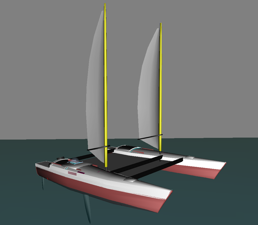
Conventional monohulls have their masts amidships, and modern catamarans having been evolved by people used to monohulls started by adopting monohull rigs. There is an obvious alternative, which is to place one rig on each hull. Apart from the famous and ill fated Team Phillips, there have been any number of successful biplane rigged catamarans, such as these:
The biplane rig allows us to unload the mast foot stresses from the main beam without the complexity of the stress frame. It also neatly divides the sail area up into smaller, more easily handled units and brings the centre of effort down, reducing the capsizing couple.
The stress frame, of course, did not only serve to eliminate the main beam; it removed the high loads of rigging (and particularly forestay) attachments from unfair positions on the hulls. With the biplane rig, the question arises whether to stay it, and if so how - there isn't much width to stay a biplane rig on its outboard side.
Of course you can stay the rigs on the inboard side only and put a compression strut between the hounds of the two masts, but once again complexity is creeping up. An unstayed biplane rig looks at least interesting enough to be worth considering.
 Burial and Bearing
A mast has a lot of leverage. To transfer the loads on a mast into the structure of the boat needs connections which can handle a lot of strain. With an unstayed mast, the further you can bury it into the structure the better. This is particularly true if you want a rotating mast - the greater the distance between the upper and lower bearing, the less the strain on each. The problem is that there isn't much room in a 10 metre catamaran hull anyway, and the mast needs to come through quite close to the midpoint of what accommodation volume you might have, effectively dividing it into two. It would obviously be nicer if we could move the mast foot out of the hull... and the present sketches show the mast foot in the punt. The problem is that this gives only 600mm of bury. Moving the mast into the hull proper would reduce the width of the berth, which is already only 700mm wide.
Leaving that problem on one side for the moment, there are two ways the sails could be deployed on the unstayed biplane masts.
They could be sleeve luff, in which case the masts don't have to rotate. But if they are then either they must be loose footed in which case it's hard to get an efficient shape off the wind, or they must have a conventional boom which will sweep low across the companion hatches, endangering people's skulls. Also, with a conventional boom, you need to do something about twist and that something means in effect a kicker and that's quite awkward to arrange without moving the centre of effort up. You can't easily have an angled wishbone boom with a sleeve luff sail, because reefing becomes exceedingly awkward.
Otherwise, the sails could be hoisted in tracks or luff grooves. In this case it's possible to have an angled wishbone boom which reduces the risk of concussion and eliminates the problem of twist; however, unless the mast rotates, you'll get a lot of turbulence on the lee side.
 The Stub
So, how to arrange a rotating, unstayed 8.5 metre mast with a bury of only 600mm? The bearing loads look completely unfeasible. Any play in the bearing is going to allow the whole rig to bang about horribly in a seaway, causing further damage to the bearings and putting stress on the whole boat.
The solution seems to me to be to turn the problem on its head. Instead of burying the bearings in the boat, place them in the mast, so that the rotating wing unit rotates on a spindle of a stub mast permanently bonded into the hull structure. This allows planety of separation between the upper and lower bearings - my present sketch has them over two metres apart. The stub of course still only has 600mm bury into the hull structure, but because it is permanently bondedthere is no slop in the joint and there are no compromises consequent on a need for demountability. At present this looks to me like a feasible solution.
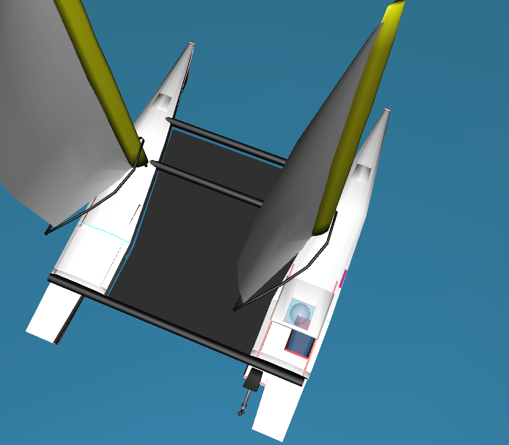
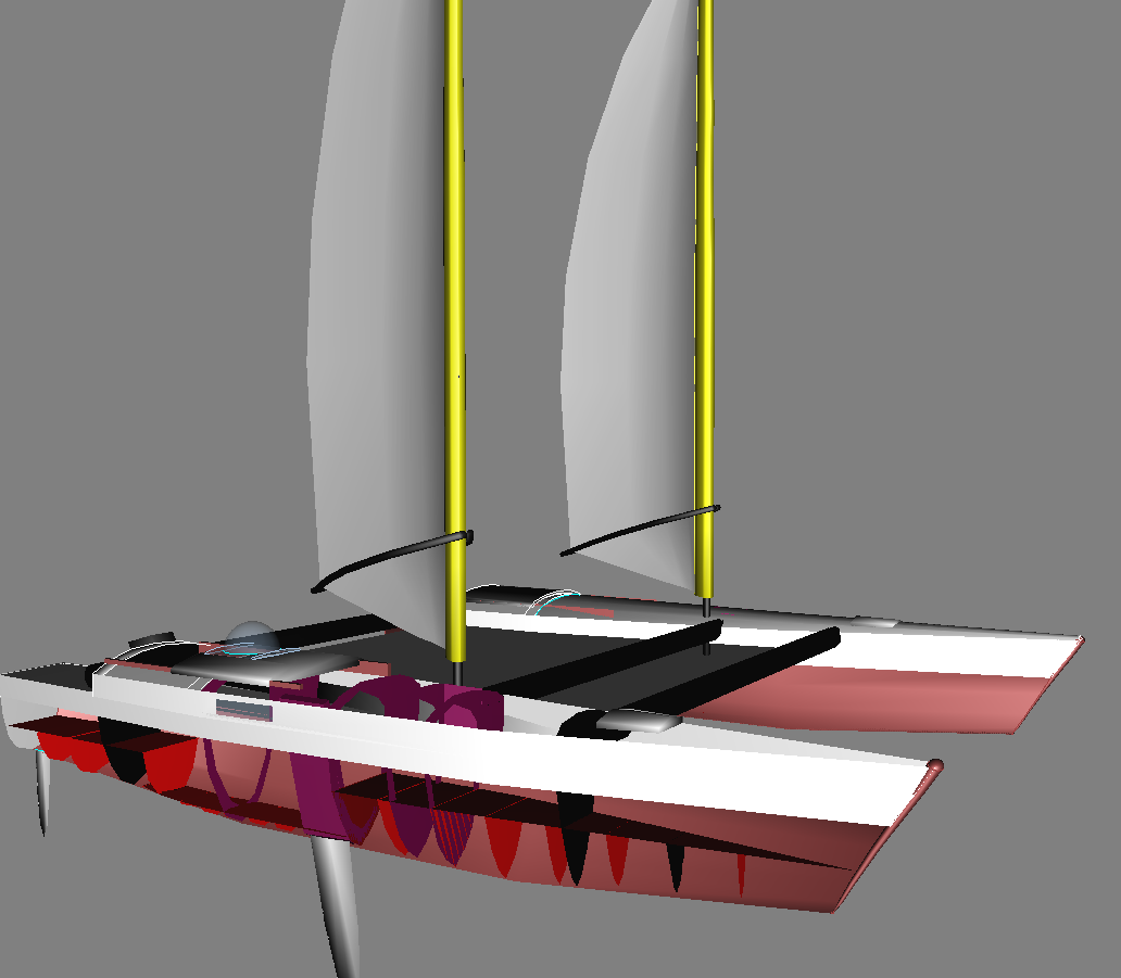 Implications for the platform
The only implication that the biplane rig really has for the platform is that it makes it simpler. The stress frame is gone, and consequently the angled bulkheads are no longer needed. On the other hand a good deal of structure is needed to transfer loads from the feet of the stub masts to the hull, and consequently an additional pair of bulkhead has been added, one immediately behind the mast foot and one immediately in front of the short centre beam, which in turn is immediately in front of the mast foot. A three dimensional plywood eggbox structure fills the volume between the floor of the punt, the coachroof, the outer edge of the punt and the inner edge of the hull between these bulkheads, providing reinforcement and transmitting loads from the mast foot and beam socket to the hull.
give me feedback on this page // show other people's feedback on this page