
 Having sailed Dances with Waves
for a season, I've come to the conclusion that one of the things that needs
to be changed is the cockpit box. The present cockpit is just a rectangular
box slung between the crossbeams. The box has a hole cut in the bottom for
the outboard bracket, and the bracket itself bisects the hole, extending down
below the box. At speeds above ten knots, the bow-wave intermittently hits
the forward side of the outboard bracket, and explodes up through the hole,
soaking everyone in the cockpit. Additionally, the floor of the box is
supported on the underside by transverse wooden beams, ideally placed to
catch wavetops and slow the boat. Furthermore, the cockpit box does not fill
the gap between the hulls, it sits in the centre of it, with loose plywood
seat panels bridging the gap. These never have yet been disloged as a result
of wind or wave action, but they clearly could, and the result would be
dangerous. The space below these seat panels is wasted. Finally, the petrol
tank takes up a considerable amount of space in the cockpit.
Having sailed Dances with Waves
for a season, I've come to the conclusion that one of the things that needs
to be changed is the cockpit box. The present cockpit is just a rectangular
box slung between the crossbeams. The box has a hole cut in the bottom for
the outboard bracket, and the bracket itself bisects the hole, extending down
below the box. At speeds above ten knots, the bow-wave intermittently hits
the forward side of the outboard bracket, and explodes up through the hole,
soaking everyone in the cockpit. Additionally, the floor of the box is
supported on the underside by transverse wooden beams, ideally placed to
catch wavetops and slow the boat. Furthermore, the cockpit box does not fill
the gap between the hulls, it sits in the centre of it, with loose plywood
seat panels bridging the gap. These never have yet been disloged as a result
of wind or wave action, but they clearly could, and the result would be
dangerous. The space below these seat panels is wasted. Finally, the petrol
tank takes up a considerable amount of space in the cockpit.
In an ideal world, if I wasn't constrained by time and cost (or if I was building from scratch) I would make the beams integral to the boat and the cockpit box integral to the beams as one single structure. However, what I'm seeking to achieve is the most benefit with the least change, and for that reason I'm considering just replacing the cockpit box as a single module. This means that the new design has to work in with the constraints of a demountable boat which when assembled is still to some extent flexible. Limited flexing of the boat around the crossbeam mounting blocks must not cause the cockpit box to bind on any part of the hulls, causing damage either to the hulls or to the box.
The height off the water of the bottom of the outboard bracket is constrained by the length of the outboard leg. It cannot be any higher. So if it is to be prevented from slamming into the tops of waves it must be faired. If it is to be faired then the fairing provides a potential home for the petrol tank below the cockpit floor. However, if the outboard bracket is to be faired it makes sense at the same time to fair the supporting structure of the cockpit floor.. What I'm proposing is a boatlike fairing extending under the whole cockpit, and extending out at the sides under the loose seat panels. The intention is that the fairing should not completely fill the space between the hulls, leaving about 50mm on each side to prevent having to do some very accurate carpentry. The existing loose seat panels would then sit on the new cockpit box, covering the lateral extension of the fairing (which then serves as under-seat lockers) and the remaining (small) gap between the cockpit box and the hulls.
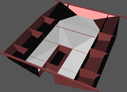
 What I propose to build is an egg-box structure,, with a
floor of 9mm water and boil proof ply supported by five transverse and four
longitudinal bulkheads of 6mm WBP ply bonded to the floor with epoxy and
filleted. Limber holes allow water to drain into the middle and then aft.
Once the bulkheads are assembled to the floor the whole assembly is
flowcoated with epoxy. Then a skin of 3mm WBP ply, pre flowcoated, is fitted
and epoxied to one half of the underside. Fillets are added where
practicable.The second half bottom skin is then assembled and taped to the
first with 100mm woven glass tape. Again fillets are fitted where
practicable. Side panels, also in 3mm, are added, epoxied and filletted to
the bulkheads and taped and filletted to the bottom skin.
What I propose to build is an egg-box structure,, with a
floor of 9mm water and boil proof ply supported by five transverse and four
longitudinal bulkheads of 6mm WBP ply bonded to the floor with epoxy and
filleted. Limber holes allow water to drain into the middle and then aft.
Once the bulkheads are assembled to the floor the whole assembly is
flowcoated with epoxy. Then a skin of 3mm WBP ply, pre flowcoated, is fitted
and epoxied to one half of the underside. Fillets are added where
practicable.The second half bottom skin is then assembled and taped to the
first with 100mm woven glass tape. Again fillets are fitted where
practicable. Side panels, also in 3mm, are added, epoxied and filletted to
the bulkheads and taped and filletted to the bottom skin.
The assembly now resembles a very wide pram dinghy with an outboard well. The bulkhead where the outboard motor will mount is reinforced with three layers of 9mm WBP ply, one on the outside and two on the inside. 'Gunwhales' of 12x25mm softwood are assembled along the top edges of the side panels and longitudinal bulkheads to support and protect the edge of the plywood, and a mechanism, probably 30mm square softwood crossbeams as on the existing design, added to allow the structure to be assembled to the boat. Two transverse floors of 12mm softwood are fitted and epoxied across the bottom of the petrol tank well to support the tank and prevent abrasion damage to the bottom skins. A loose hatchcover of 9mm ply to cover the petrol tank well completes the structure.
There are still things I'm not completely sure of with this design. I've suggested 3mm ply for the bottom skin. This, in theory anyway, ought to take no load except the occasional wave top - it's protected from anything else by the hulls and is well above the waterline. Nevertheless occasionally wavetops can slam very hard, and I'm not sure that 3mm is really enough. Of course if it fails it isn't critical because it's only a fairing and isn't structural. It would be possible to reinforce the bottom by sheathing it in fibreglass, but that would add weight and the new cockpit structure is already inevitably going to be heavier than the old.
On these schematics I haven't shown a central longitudinal bulkhead. This (if fitted) would make assembly of the bottom skins easier and would add a little strength to the structure but it would also add weight and I'm not convinced that it's needed.
It would be possible to completely seal the under-floor compartments of the egg-box. In my initial sketches the cockpit box could act as a boat in its own right and serve as a rigid liferaft in the event of capsize or serious failure of the boat's structure. If you were to take this idea seriously you would have to seal the under-floor compartments and you'd have to provide proper tops to the side compartments which are left open ('under-seat lockers') in the schematic. My problem with that is that it's impossible to inspect these compartments unless inspection hatches are fitted in the cockpit floor, where they would be a nuisance underfoot, and if they were sealed then if a crack somewhere let (for example rain) water in it would be impossible to get it out. So I'm suggesting a series of limber holes, linking each side compartment with the adjacent under-floor compartment and each under-floor compartment to the petrol tank well, where a bung in the bottom of the motor bracket can let it out. This of course means that the cockpit box would not be usable as a liferaft, because, laoded by itself, the bracket top would be close to the waterline and the underfloor compartments would flood.
Of course if anyone else wants to play with the cockpit-box-as-liferaft concept you're welcome - it would certainly make a larger and more durable liferaft than any inflatable one you could conveniently carry, and a folding canvas hood would not be hard to arrange (and might, indeed, be useful as a cuddy when sailing).
The seat panels will still be loose, although they may have lanyards retaining them to the new cockpit box. This isn't ideal, but I can't see a way of hinging them which will not interfere with the flexing of the boat.
I haven't shown bins for halyard tails on the schematic, but they would be fitted much as on the existing box.
give me feedback on this page // show other people's feedback on this page