By: Simon Brooke :: 3 September 2025
Details, details
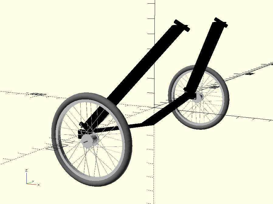
Thinking about how the tricycle will go together means thinking about a lot of details. One of the first thing that needs thinking about in detail is the four-bar linkage, since if that does not work the whole idea does not work and there's no point in investing quite a lot of money in laying up the hull.
Four Bar Linkage
The principle of a four bar linkage is that you have four real pivot axes, which are constrained to be parallel to one another by the bars of the linkage, but can move around one another as constrained by the bars of the linkage, to produce an overall movement around a fifth pivot axis, also parallel with them, which isn't really there. All right so far?
So, in our linkage, one of the 'bars' is the hull of the tricycle, or more specifically a line through the roll-over bulkhead in the hull of the tricycle, behind the rider's shoulders. Two of the legs run from the pivots behind the shoulders to pivots by the hubs of the rear wheels. The fourth bar is an axle beam which runs between the hubs of the rear wheels, and which must pass freely below the hull (and must not touch it).
Triangulating the legs
However, around half of the total weight of the tricycle, the rider and any cargo will be transferred to the rear wheels through those legs. But because we need the virtual pivot axis to intersect the ground plane in front of the contact patch of the front wheel, all the axes (because they must be parallel with one another) must slope quite sharply down towards the front; somewhere around 45°.
That puts a considerable unfair load on the pivot. I believe that this load was the cause of steering problems in some of the Mosquito tricycles, that I described in this post. To resist that load, the upper pivot needs to be as long as possible. Which means, I think, that as well as the leg directly supporting the shoulders, there must be a brace, also pivoting around the same axis, either forward or aft of the leg, and joining with it at the pivot by the rear wheel hub.
So there are a series of problems arising.
Stand-offs for hull pivots
The shoulder pivots mount to the hull at something close to its maximum width, because the hull is a smooth envelope around the rider's body and the shoulders are about the widest part of the body. But it is a smooth envelope, and to be a smooth envelope, given the shoulders are quite far back and the hips, which are also wide, are in front of them, there almost certainly needs to be a wider part in between. So while it's possible that I can find two well separated points on the hull which are on a common axis parallel with the virtual axis, that may be quite tricky. So I may need stand-offs from the hull for one of the two pivots for each led, and that's likely to be the shoulder pivot.
I don't yet know for certain that this is necessary, but if it is the design is going to have to be quite thoughtful, because it needs to be both strong enough and aerodynamically clean.
Knuckles
The legs of the linkage must, in their rest position, lean in towards the hull by around 30°. They must do this, because the hull must be able to rotate between them, and the less it can rotate, the larger the turning circle of the tricycle will be. But although with the triangulated bracing I've suggested above, the legs and braces could be just tubes, you would get an undesirable amount of aerodynamic drag if they were.
So I think that the legs and braces should be aerofoil section. Laying up carbon fibre aerofoils over either polystyrene or 3D printed cores is done in the model aircraft community, and seems fairly easy. However...
Because the axes slope downwards, to orient the aerofoils in the plane of the axes would create drag. Instead, the aerofoils must be oriented at an angle to the axis, so there needs to be quite complicated shaped knuckles at both the upper and the lower pivots. Note that for added fun, the lower knuckle has to accept not only the leg but also the brace.
How to make these? They could be milled out of aluminium, but I don't have the skill or equipment to do that, and getting it done would be quite expensive: these are really odd shaped parts. But I think that they could be made by laying up carbon fibre over a 3D printed armature. I would need to do that experimentally, and I would have to do it soon, because if it doesn't work I'm going to have to think again.
I think the basic structure is like this: I but some industrially manufactured carbon fibre tube whose internal diameter is identical to the external diameter of the bushes or bearings I decide to use.
If, for example, I decide to use 6mm pivot shafts, I can get 15mm outside diameter sealed bearings which would be a push fit into 18mm outside diameter carbon fibre tube. That would end up with quite a chunky knuckle, because that 18mm tube has then to be wrapped with a further two wraps of carbon fibre twill to bind it into the knuckle body for a final outside diameter of the tube part of about 20mm. The other end of the knuckle from the tube is an aerofoil stub sized so that when wrapped with four layers of carbon twill it is identical in section to the polystyrene core over which the leg aerofoil is to be laid up.
Laying up the legs
My plan for making the legs is then as follows. The armatures for the upper and lower knuckles are 3D printed, and the foam core for the aerofoil section is hot-wire cut to shape, and then cut to length. The tube sections are cut to length to fit the armatures, and are then bound on to the armatures with 90mm wide strips of carbon twill, one running from the aerofoil end, over the tube, and back to the aerofoil end; then one wrapped round the aerofoil end; then one like the first one; then a final one round the aerofoil end. Each strip is wet out with hand-brushed epoxy as it is laid on. Then the whole thing is put in a vacuum bag and left until the epoxy is more than half cured.
A clean table top of appropriate size is prepared (this isn't huge, the legs are approximately 600mm overall length), a piece of mylar film is laid on it, the layup for the aerofoil is prepared and wet out on the mylar film, the foam core is laid onto the layup. The knuckles are taken out of their vacuum bags, butted up to their appropriate ends of the foam core, and the mylar film with the layup folded over the whole thing.
I think this will work. I've not tried, and I haven't seen any evidence of anyone else having tried anything similar. It's not so expensive and elaborate that I can't afford to prototype it. My idea of assembling the whole thing before the knuckles are fully cured is so that the epoxy on the aerofoil will fully chemically bond to epoxy on the knuckles; but if that doesn't work then I may need to let the knuckles fully cure, abrade them to provide a mechanical key, and probably assemble them to the foam core with dowels, before wrapping the core.
Ideally I'd like to have a pre-prepared jig which would hold the upper and lower tubes exactly parallel to one another while the resin was curing, but it's hard to see how such a jig could be compatible with a vacuum bag.
Whether the knuckles are assembled to the core before they are fully cured or after, the layup which wraps the core must be cut long enough that it also wraps the aerofoil ends of the knuckles into one single continuous structure. Whether I can effectively vacuum bag that structure I simply don't know; it may not be possible.
On further thought it would be possible to mould the armature for the knuckles with dowels which would stick into the ends of the foam core, and to make a template so that holes could be drilled for the dowels in precisely the right places. That would give the assembly far more structural integrity while the epoxy cured, and consequently would make vacuum bagging less of a risk.
Assembling the braces to the legs
Trying to fit the brace into the lower knuckle at the same time as the leg, while the epoxy is wet and the assembly is floppy and vulnerable, seems to me a fool move. The upper pivots need to line up precisely and to be precisely spaced, and I think that's asking a lot. So I think the leg assemblies, with the knuckles attached, should be allowed to cure without the braces, although the precise detail of how the brace bonds to the lower knuckle is something I'm still working on.
The layup of the brace is probably similar to that of the leg, except it is assembled only to an upper knuckle (because it will assemble to the lower knuckle on the leg).
The bearings or bushes should be assembled into the ends of the upper tube, with an appropriate length spacer between them (if that spacer can be glued in, so much the better).
Then a piece of 6mm threaded rod, longer than the overall distance between the two pivot points on the hull, and nuts screwed on to locate the leg firmly at one end of the rod. Then the bearing(s?) in the upper knuckle of the brace are installed similarly, and are threaded onto the other end of the rod and locked at precisely the right spacing.
Then whatever is needed to bond the brace into the lower knuckle is done — and again, this is a detail I still need to work on.
The axle beam
The axle beam has to pass under the rear of the hull. That's where cargo space is, so the bottom of the hull can't be raised too much, so the beam has to be lower in the centre than the axles of the wheels. So it has to have a bend or an angle. It also needs to be reasonably aerodynamic. A profile and method of construction similar to the legs of the linkage seems appropriate, but this too needs more thought.
Steering
You steer this vehicle by pulling the hull from side to side along the axle beam, or, seen the other way, by pulling the axle beam from side to side beneath the hull. The Mosquito trikes did this with an enormous plywood quadrant moved by the steering handles, joined to the ends of the beam by stretched wires, and that system is a possibility.
However, the steering issues on the Mosquitoes worries me, and it's far from the only solution. Firstly, actual handlebars in front of the rider's hands, as Seventy Seven has, or a joystick as Mike Burrows' Windcheetahs have, would be possible. I certainly remember that I found the Windcheetah joystick very intuitive and pleasant to use, and it could simply turn a rod passing under the rider's seat, with a bell-crank on the end to move the axle beam. Whether that would give enough motion I don't know yet, but I think so. The other thing I'm tempted to try is a double acting hydraulic ram, although, of course, a very light one!
Electronics and instruments
I want this machine to be a strictly legal electrically assisted cycle, so the motor must be powered only when the rider is actively pedalling. This means, when there is tension on the primary drive chain, because, if I have the motor on the cross-shaft as I intend to, there will always be tension in the secondary chain when the motor is running.
The Bafang motor which I'm thinking of using has a control system which isn't very good at strictly road legal, and which is designed to mount in the way that I'm mounting it. So I'm wondering whether I'm gaining any value in buying a motor which is packaged for bicycle use but not in the way I intend to use it.
In any case I want a rear camera rather than a rear view mirror, and because of limited space for mounting a screen near the rider's eye line I would like the camera display to be the same display as the instrument display. So I'm thinking a raspberry pi or similar, with a smaller-than-phone sized display, mounted on the rear leg of the subframe. That needs to do
- speedometer (hall-effect sensor on the subframe reading a magnet on the front wheel, plus counter; or else a GPS receiver);
- battery status (voltmeter?);
- 'mirror' (reversed display of the rear view camera).
It would be really nice if it could do motor control as well, but if not, having the motor controller mounted somewhere else is not impossible.
Other thoughts
Again, just to capture it for now: if I can get custom lathe work done (which I probably can), it would be really nice to do a single sided front hub in two parts, a rotating spindle which is not removed from the vehicle when the wheel is removed, so that the chain remains in place, and a shell which keys onto that spindle in some way onto which the wheel itself is built.
However, even with a one-sided hub, removing the front wheel from the vehicle won't be easy, so I get back to the idea that in the event of a front wheel puncture that I can't fix with the wheel in the vehicle, I just call on a man with a van. That's a fairly large van; the hull needs to be between 2.3 and 2.5 metres long, although the overall width of the vehicle doesn't need to exceed one metre, I believe. But I do have friends with fairly large vans, so not impossible.
I have thought about whether belts should be preferred to chains, but I think not; I think the losses on chain drive are lower, and, given that the chains will run wholly within the hull, they should stay pretty clean.